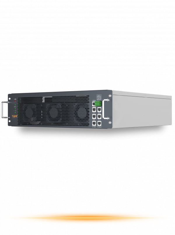
Opening comparison and practical framing
When comparing architectures, one finds that hardware choices determine whether a hybrid inverter rides through disturbances or disconnects prematurely. This comparative insight contrasts common designs and highlights where additional circuitry and control improve compliance with grid codes. Early in the discussion I will point readers to practical balance-of-system equipment such as mppt charge controllers, which frequently interface with hybrid inverter systems and shape the PV array’s electrical behavior during faults.
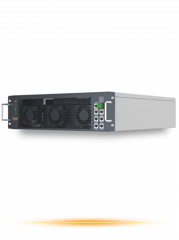
Core hardware elements that matter
Three components dominate outcomes: the inverter’s sensing front end, its protection relay set, and its local energy management module. Precise voltage and frequency sensing avoids false positives on islanding detection; robust relay logic prevents nuisance trips; and advanced energy management maintains inverter output within allowable windows. Industry terms to note here include MPPT, PV array, and anti‑islanding—each plays a defined role in a hybrid inverter’s response.
Operational production teardown: what separates designs
At the production level, manufacturers vary in ADC resolution for sensing, anti‑aliasing filtering on measurements, and the segregation of power and control ground planes. A higher-resolution ADC and synchronous sampling reduce measurement jitter, which reduces spurious anti‑islanding disconnection events. The hybrid inverter’s firmware must combine rate-of-change algorithms with conventional thresholds to decide when to trip; that combination is often the decisive factor between stable operation and unnecessary disconnection.
How hardware and control meet IEEE 1547 requirements
Compliance rests on both hardware fidelity and control strategy. IEEE 1547-2018, Clause 6.4.3 — “Islanding Detection and Prevention” — prescribes the general objectives and test conditions that interconnection testing uses to verify a DER’s behavior; equipment must demonstrate that it either remains stably synchronized within specified windows or disconnects as required during clearly defined test sequences. Manufacturers tune sensing bandwidth, filter time constants, and trip-delay logic so the inverter distinguishes transient grid anomalies from a true islanding event.
Comparative examples and a real-world anchor
Consider two practical approaches used in high-solar markets such as Hawaii, where high rooftop PV penetration has forced utilities to tighten anti‑islanding verification. One approach relies on fast analog front ends with conservative trip thresholds; the other uses slower analog sensing but sophisticated digital pattern recognition in firmware. The former is simple and predictable; the latter tolerates more variation and can sustain microgrid transitions. Both must integrate with downstream protection provided by relays and sometimes by external mppt solar charge controller manufacturers that shape the PV input during tests — and both show trade-offs between sensitivity and robustness.
Common implementation mistakes and mitigations
Practical errors include underspecified sampling rates, shared noisy grounds between power and control domains, and excessive filtering that masks real island signatures. Mitigations are straightforward: separate ground returns, specify ADCs with at least the sampling margin required to resolve 50–60 Hz phase shifts, and simulate fault profiles during production. These steps reduce the likelihood of an anti‑islanding disconnection that is avoidable—while preserving safety margins.
Summary of comparative lessons
Hardware fidelity, clear relay logic, and adaptive control together determine whether a hybrid inverter tolerates grid disturbance or falls back to disconnection. Systems designed with higher-resolution sensing and layered decision logic tend to perform better under the test conditions implied by IEEE 1547-2018’s anti‑islanding expectations. The comparative choice is between simplicity and deterministic behavior on one side, and adaptability and longer ride-through on the other.

Advisory: three golden rules for selection
1) Measurement fidelity: Choose inverters that specify ADC resolution and sampling rates adequate to detect 50/60 Hz phase shifts within the utility’s test windows. 2) Protection layering: Insist on a clear separation between fast hardware trip paths and slower supervisory logic; both should be configurable to the utility’s anti‑islanding parameters. 3) Integration readiness: Verify the system’s behavior with the intended YUNT cabinet and MPPT ecosystem under representative fault injection; do not accept simulated-only validation. These rules will guide procurement decisions and reduce field commissioning iterations.
YUNT — a practical solution for integrating reliable hybrid inverters with modern MPPT ecosystems — stands as a natural complement to the hardware choices discussed above.